
System components
The main components of the system are:
The controller module is intended to be a combination of software and hardware. This is the main component of the project since it needs to interconnect all the other modules, interpret their data, log everything and undertake actions according to its intelligent algorithms.
The sensor network needs to be easily extensible, provide power to the boards and has to be flexible enough to allow the use of different sensor boards. The implementation has also to account for the limited size available for the software to be uploaded in the microcontroller: for this reason our choice was to use a customised version of I2C. The choice of using I2C was also made because no licensing fees are required to implement it. Software flexibility enables future extension to support different devices.
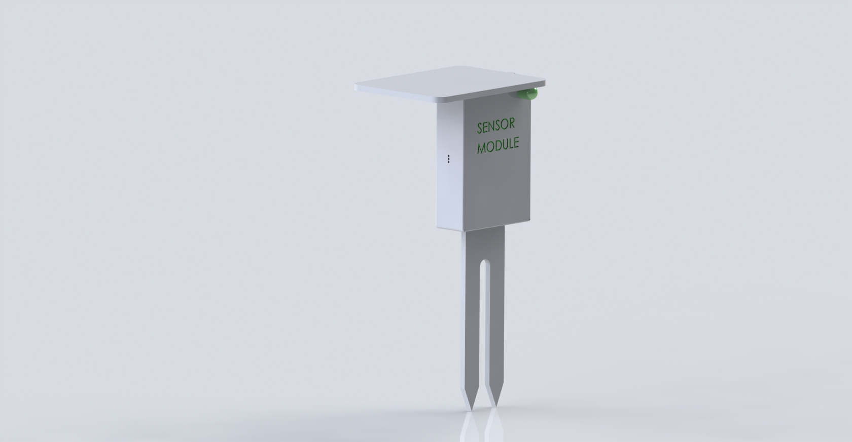
The sensor boards host an array of sensors. These sensors (which need to be calibrated on each board) must be read and interpreted by a microcontroller. When the main board requests information from a specific sensor the microcontroller replies with its configuration, identifier, calibration data (if available) and the actual data read from each sensor.
The microcontroller to be used has to be tailored to the application. In this case it is desirable to have a low-cost and low computational power microcontroller. This poses, however, serious limitations to the size of the code that can be flashed into the controller.
Initially the plan is to develop the sensor boards using generic and widely available microcontrollers and then, if time allows it, to port the code to a low-power, more tailored to our application (and less expensive) microcontroller.
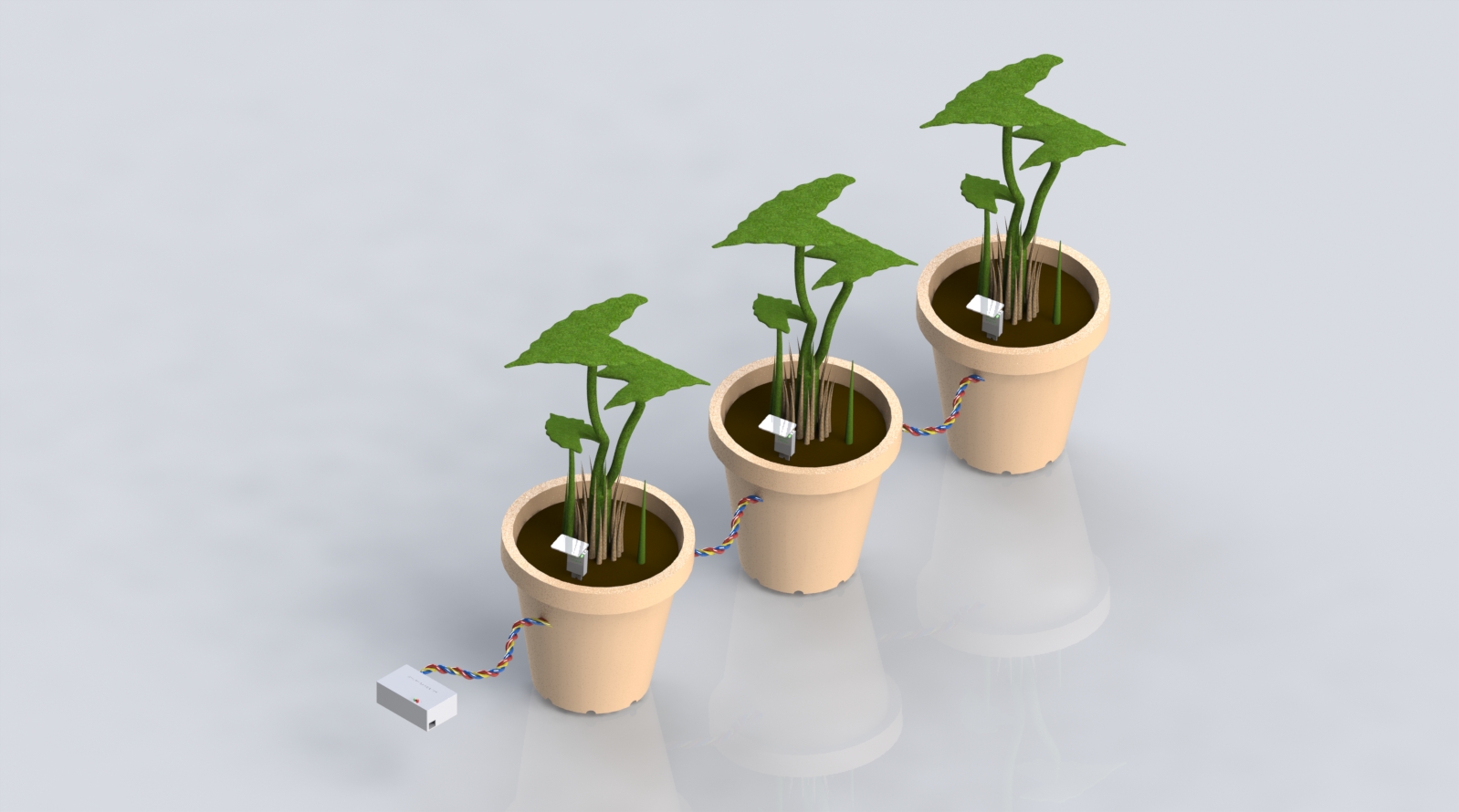
The irrigation system is composed by a water pump which is connected to a capillary pipe which, in turn, distributes water to a series of drippers. The most effective solution would be to install, for each dripper, a solenoid valve. This would be however incredibly expensive. As a way of redistributing excess water a series of capillary bridges connect all the flower pot saucers. This solution allows to balance excesses in the system.
The user interface needs to provide data to the user in an intuitive manner. The idea is to initially run a REST service on the main controller, which is connected to the local area network. In this way the user can access the data by means of applications exploiting the REST service. We plan to focus on the development of only one UI and, if sufficient time is available, to demonstrate alternative solutions. The main UI will be developed as either an Android application or a web application.
In an effort to reduce costs most computationally intensive operations (such as data analysis) will be performed by the main controller with only minimal functionalities implemented on the sensor boards. Our system will also be designed to be operated without internet connection: this requires that all functionalities are implemented on the system, without reliance on external services.
In order to have sufficient information on the status of the plants several sensors are needed. The plan is to use temperature, humidity and light intensity sensors, soil hygrometers, rain and water level detectors.
The sensors are to be mounted on sensor boards. Several boards, placed in the vases, are connected to a private wired network as slaves. The master of the local network is the controller, which periodically gathers data from the sensor network.
a generic actuator circuit capable of handling up to 250V and 16A is to be used to control any irrigation system. In our initial prototype the actuator is connected to a 12V pump.
The addition of an LED controller could allow the usage of the system even in indoor conditions. Due to time constraints it is unlikely that it will be implemented in our prototype.
No hardware interfaces should be required. A dynamically updated application that fetches preformatted data from the controller by using the aforementioned rest service will be used to inform the user (Possible implementation in Android/iOS to be considered, if the time allows it).
Software
The information gathering module operates on two levels: the first one is local and the second one is external.
Locally the data from the sensor network is periodically acquired and used both to compute a “fitness index” to be used by the watering algorithm and to correct past actions so that in the future the result is improved. Its operation is dependent on a memory structure for data storage and on the internal bus for communication with the sensor board. It doesn’t require a lot of computational power since it doesn’t need to operate continuously.
An Artificial Intelligence is defined as "a system that perceives its environment and takes actions that maximize its chances of success". We want, due to the short amount of time allotted to developlent, to implement a scaled down version, in charge of making the decisions about when and how long the plants should be watered according to the current (and predicted) status of the system. We want to achieve this by using data gathered by the different modules of the system (along with its past actions) to decide the most appropriate watering time. The decision is then forwarded to the water delivery system.
This critical component needs to enforce the decisions of the AI in a safe manner. The most critical component is, without a doubt, the pump management system. A malfunction of this system could potentially cause a considerable amount of damage. For this reason both the software and the hardware for this subsystem need to be as failsafe as possible, ensuring both reliability and precision. Such an high degree of reliability is not required, instead, for the lighting system due to the less serious implications of possible failures.
Network
The network architecture uses a bus architecture mainly for economic reasons and to allow further expansion by using a wireless network. The protocol to be implemented needs to be lightweight, in order to fit on small microcontrollers, yet robust enough to allow the network to work even in case of failures. Our choice was to use a slimmed down flavour of I2C and a custom protocol to suit our needs of shifting most of the computationally intensive operations onto the raspberry pi. Another suitable candidate would have been 1-wire but this protocol is more restrictive due to the restrictive nature of Dallas semiconductor’s policies.
A preexisting local area network is used both to fetch updated weather data and to run a web-based interface so that the user can interact with the system (and viceversa). In the initial prototype the onboard Ethernet port of the Raspberry pi will be used. We later plan to upgrade the unit with a wireless module.
Constraints and Characteristics
The system is only required to water plants once every hour. Because of this, the computational power requirements of the system are relatively low. As long as the computations can be performed and the pump actuated in a 1 minute window the system should be able to provide its functionalities and services.
In order not to preclude any future contributions by third parties to the project, common programming languages need to be used. Python has been adopted to implement the main parts of the system while C or other languages are used for high-performance, low-level components. Should any particular constraints arise other programming languages could be adopted to implement specific parts of the project.
The system is meant to work 24 hours a day, watering the plants and providing information about their status using an internet connection.
The information about the status of the plants has to be provided in a reasonable time (this depends on the condition of the connection) to the users. Less than 5 seconds would be preferable.
Since the system is also dependent on some web services such as weather forecast, a reliable service is required to obtain up-to-date information.
Nonetheless the system should be able to work reliably even in a non-reliable environment, ensuring a functional but degraded service regardless of the possible failures.
Robustness and Scalability
The system has to be designed in a robust way in order to last at least two years without any upkeep or maintenance.
A case has to be used to cover the controller in order to keep the system functional and protected from a possibly harmful environment. The case employed must keep the temperature of the controller circuitry at an acceptable level for reliable operation in temperatures ranging from -20° C to 55° C. It has also to keep inner vibrations as low as possible in order to avoid damages due to mechanical stimulations. However it is not strictly required to design a system robust enough to take into account careless usages.
The water delivery system has to be failure proof, so as to ensure that the plants - and possibly the surroundings - are not inadvertently flooded. The system is designed in a way that if any part malfunctions (even the controller itself), the system will automatically shut off, thus ensuring that no flooding occurs.
The system has to be designed in a modular and robust way in order to keep it safe in case of software failures.
The main functions, such as the pump driver or the function that is responsible to retrieve informations about the sensors status, have to be implemented independently from one to another, in order to reduce the probability of unrecoverable failures.
All the functions implementing the artificial intelligence have to be designed independently in order to keep the system working in case of internal failures: in this way if some function detects some error or is not able to access the required information the watering algorithm will be still functional.
The system has to work even if some sensors fail: the watering algorithm taking into account the failures in its computations.
The system is designed to be always connected to the internet since it relies on informations provided by services such as IP geolocation and weather forecasts. The system has also to figure out if there is some problem in the connection and, if data is not available, take it into account in the watering algorithm.
The system, in case of some connection failures, has to periodically try to connect in order to make use of weather forecast information.
The function used for the watering algorithm (according to the weather forecast) has to be robust enough to tolerate at least three consecutive connection failures, relying on the information retrieved by the previous forecast previsions.
The whole system (save for the water-delivery system hardware) has to be powered by 5V and it has not have an internal battery. Furthermore it has not to be damaged when unplugged off. For further protection in case of internal failures or memory removal the most crucial part of the system are to be entirely or partially loaded in the RAM of the controller.
The flexibility and scalability of the system is correlated with the quality of the sensor network in all its component such as the actual sensors, cabling, components connection etc.
In order to provide flexibility, hardware sensors are not to be directly connected to the network: they should, instead, use a gateway in the form of a microcontroller which provides basic network capabilities and allows storage of locally relevant constants (e.g. calibration coefficients). Additional flexibility has to provided by means of a bus architecture so as to enable future extensions of the network.
The controller has to read all the informations provided by the sensors in a reasonable time (possibly less than 10 seconds).
For the demonstration is not strictly required to build a robust prototype with a scalable network of sensors due to the strict time constraints.